The eddy current sensor can measure static and dynamic non-contact, high linearity, high resolution measurements of the distance of the metal conductor under test from the probe surface. It is a non-contact linearization metrology tool . The eddy current sensor can accurately measure the static and dynamic relative displacement changes between the measured body (must be a metal conductor) and the end face of the probe .
In the state analysis, vibration research, and analysis of high-speed rotating machinery and reciprocating motion machines, various parameters of rotor vibration state can be continuously and accurately acquired for non-contact high-precision vibration and displacement signals. Such as shaft radial vibration, amplitude and axial position. From the theoretical analysis of rotor dynamics and bearing science, the state of motion of a large-scale rotating machine mainly depends on its core—spindle—while the eddy current sensor can directly measure the state of the shaft without contact, and the imbalance and misalignment of the rotor, such as a rotor. Early identification of mechanical problems such as bearing wear, shaft cracks, and friction can provide critical information. The eddy current sensor has the advantages of long-term operation reliability, wide measurement range, high sensitivity, high resolution, fast response, strong anti-interference force, free from the influence of oil and other media, simple structure, etc., in the state of large rotating machinery. Online monitoring and fault diagnosis are widely used.
According to Faraday's principle of electromagnetic induction, when a bulk metal conductor is placed in a changing magnetic field or when it is moved in a magnetic field (whether the metal is lumpy or not, and there is no eddy current when cutting a non-changing magnetic field), a vortex will be generated in the conductor. Rotating induction current, this current is called eddy current, the above phenomenon is called eddy current effect. The sensor made by the eddy current effect is called an eddy current sensor.
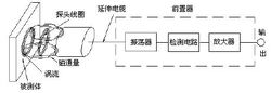
The front-end high-frequency oscillating current flows into the probe coil through the extension cable, and generates an alternating magnetic field in the coil of the probe head. When the measured metal body is close to this magnetic field, an induced current is generated on the metal surface. At the same time, the eddy current field also generates an alternating magnetic field having a direction opposite to the direction of the head coil. Because of its reaction, the head coil is high. The amplitude and phase of the frequency current are changed (effective impedance of the coil),
This change is related to parameters such as the permeability of the metal body, the electrical conductivity, the geometry of the coil, the geometry, the frequency of the current, and the distance from the head coil to the surface of the metal conductor. Assuming that the metal conductor is uniform in material and its performance is linear and isomorphic, the physical properties of the coil and metal conductor system can be determined from the conductivity σ of the metal conductor, the permeability ξ, the size factor τ, the head body coil and the surface of the metal conductor. Distance D, current intensity I, and frequency ω parameters are described. The coil characteristic impedance can be represented by the function Z=F(τ, ξ, б, D, I, ω). Generally, we can control the parameters τ, ξ, б, I, ω to be constant within a certain range. Then the characteristic impedance Z of the coil becomes a single-valued function of the distance D, although its entire function is nonlinear. The function is characterized by an "S" curve, but it can be chosen to be a segment that is approximately linear. Here, the change in the coil impedance Z, that is, the change in the distance D between the head body coil and the metal conductor is converted into a change in voltage or current by the processing of the driver electronics. The size of the output signal varies with the distance between the probe and the surface of the measured object. The eddy current sensor is based on this principle to measure the displacement and vibration of metal objects.
When the distance between the measured metal and the probe changes, the Q value of the coil in the probe also changes, and the change of the Q value causes the amplitude of the oscillating voltage to change, and this oscillating voltage with distance changes through detection, filtering, and linear compensation. The normalized amplification process converts into a change in voltage (current), and finally the mechanical displacement (gap) is converted into a voltage (current). From the above, the measured body in an eddy current sensor working system can be regarded as one half of the sensor system, that is, the performance of an eddy current displacement sensor is related to the measured body. The eddy current sensor works as shown
According to the penetration of the eddy current in the conductor, this sensor can be divided into high-frequency reflection type and low-frequency transmission type, but it is still similar from the basic working principle. The greatest feature of the eddy current sensor is the non-contact continuous measurement of displacement, thickness, surface temperature, speed, stress, material damage, etc. It is also characterized by its small size, high sensitivity, and wide frequency response, and is extremely versatile.
The principle of the eddy current sensor is to accurately measure the relative position of the measured body (must be a metal conductor) and the end face of the probe through the principle of eddy current effect. Its characteristic is long-term work reliability, high sensitivity, strong anti-interference ability, non- The contact measurement, fast response, and free from the influence of oil and water, are often used for long-term real-time monitoring of shaft displacement, shaft vibration, shaft speed, etc. of large rotating machinery, which can analyze the working conditions of the equipment and the cause of failure. Effectively protect and pre-maintenance equipment.
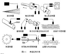
The eddy current sensor system is widely used in electric power, petroleum, chemical industry, metallurgy and other industries for its unique advantages. It has radial vibrations and shafts for shafts of large rotating machinery such as steam turbines, turbines, generators, blowers, compressors, and gear boxes. In-line measurement and safety protection for displacement, phase detector, shaft speed, differential expansion, eccentricity, and oil film thickness, as well as rotor dynamics research and part size inspection. Figure 1-1 shows some typical applications of eddy current sensors of Shanghai Aero-Vibration Instrumentation Co., Ltd. The preamplifier outputs a DC voltage that is proportional to the distance based on the change in the impedance of the probe coil [1] .
Eddy current displacement sensor
Series Integrated Eddy Current Displacement Sensor
Serial Number
form
Range
Operating temperature
Front device installation
HZ-891XL
Split (probe + preamp)
0-25mm (expandable range)
-50°C~ +175°C
Baseplate and rail mounting
HZ-891
Split (probe + preamp)
0-25mm (expandable range)
-50°C~ +175°C
Floor mounting
HZ-891YT
Integration (the front-end circuit is integrated in the probe housing)
0-25mm (expandable range)
-25°C~+85°C
Without a preamp
Special custom series
Split, integration can be
customizable
According to the product structure for different operating temperature
/
/
1, linear range, linear range, linear midpoint, nonlinear error, minimum measured surface
Probe diameter
Linear scale
(mm)
Linear range
(mm)
Linear midpoint
(mm)
Nonlinear error
Minimum measured surface (mm)
Φ5
1
0.25 to 1.25
0.75
±1%
Φ15
Φ8
2
0.50 to 2.50
1.5
±1%
Φ20
Φ11
4
1.0 to 5.0
3.0
±1%
Φ30
Φ25
12
1.5 to 13.5
7.5
±1.5%
Φ50
Φ50
25
2.5 to 27.5
15
±2%
Φ100
※ Non-linear error refers to the maximum error between the actual output value and the theoretical value (calculated according to the standard characteristic equation).
2, the average sensitivity (in the linear range of output changes in addition to the linear range)
Probe diameter output
Φ5
Φ8
Φ11
Φ25
Φ50
Negative voltage
8V/mm
8V/mm
4V/mm
0.8V/mm
0.4V/mm
4 to 20mA
16mA/mm
8mA/mm
4mA/mm
1.33mA/mm
0.64mA/mm
Average sensitivity error: ≤±5%
3. Dynamic characteristics
Frequency response: 0~10kHz
Amplitude and frequency characteristics: 0 ~ 1kHz attenuation is less than 1%, 10kHz attenuation is less than 5%
Phase frequency characteristics: 0 ~ 1kHz phase difference is less than -10 degrees, 10kHz phase difference is less than -100 degrees
4, interchangeability error ≤ 5%
5, working temperature
Probe: Operating temperature -50 ~ +175 °C Temperature drift ≤ 0.05% / °C
Front device: Operating temperature -50~ +120°C Temperature drift ≤0.05%/°C
6, the working medium: air, oil, water.
7, the maximum working pressure of the probe: 12Mpa
A, probe diameter selection
Probe diameter
Range
Head length
Φ5 0 5
1mm
5mm
Φ8 0 8
2mm
5mm
Φ11 1 1
4mm
11mm
Φ25 2 5
12mm
23mm
Φ50 5 0
25mm
37mm
B, thread specifications
Probe diameter
Metric thread
British thread
Φ5
M8×1
1/4-28
Φ8
M10×1
3/8-24
Φ11
M14×1.5
1/2-20
Φ25
M30×2
1.25-12
Φ50
M14×1.5
1/2-20
D No thread length selection
In 10mm units
Minimum thread length 0mm 0 0
Maximum thread length 250mm 2 5
Incremental amount 10mm 0 1
The non-threaded part of the probe is for ease of installation: When mounting with a screw hole, the unthreaded part of the appropriate length can reduce the length of the screw hole that needs to be screwed.
E shell length selection
In 10mm units
The minimum housing length is 20mm 0 2 ,
Maximum housing length 250mm 2 5 ,
Incremental amount 10mm 0 1
The length of the probe housing depends on the mounting position and the distance to the measured surface.
F cable length selection
0 5 0.5m 5 0 5.0m
1 0 1.0m 9 0 9.0m
Cable length selection should take into account the distance between the measured surface and the position of the driver. When using screw hole installation, it is recommended to select 05 (0.5m), 10 (1.0m), easy to ensure when the probe is rotated, the probe cable and probe can rotate together, not easy to break the cable, and the need to use extension cable, extend the cable length and The total length of the probe is 5m or 9m. Install the probe inside the machine. Select the total length of the probe to ensure that the cable connector can be located outside the machine to prevent the oil inside the machine from contaminating the connector.
"K" indicates that the cable is armored. No "K" indicates that the cable is not installed.
If the probe cable is not pipe protected, it is recommended to select the armored probe so that the probe cable is not easily damaged.
Example 1: HZ-891XLT08-M10x1-B-01-05-50 (split type: with preamplifier, cable, probe)
Said: HZ-891XL series eddy current sensor, probe diameter φ8, shell thread M10 × 1, standard installation method, no thread length 10mm, shell length 50mm, cable length 5m, without armor.
Example 2: HZ-891YT08HP-M10x1-B-01-05-50 (Integral Built-in Preamplifier Function)
Said: HZ-891XL series of integrated eddy current sensor, probe diameter φ8, shell thread M10 × 1, standard installation, no thread length 10mm, shell length 50mm, cable length 5m, without é“
Eddy current sensor systems are widely used in power, petroleum, chemical, metallurgical and other industries and some research institutes. Radial vibration, axial displacement, key phaser, shaft speed, differential expansion, eccentricity, and rotor dynamics of large rotating machinery shafts such as steam turbines, turbines, blowers, compressors, air separation machines, gear boxes, and large cooling pumps Online measurement and protection such as part size inspection.
Differential pressure measurement
Slope differential expansion measurement
Compensating differential expansion measurement
Vibration measurement
Shaft displacement measurement
Axis path measurement
Differential measurement
Dynamic expansion
Rotor dynamic radial motion analysis
Speed ​​and phase difference test
Speed ​​measurement
Surface roughness measurement
Crack measurement
Non-conductive material thickness measurement
Metal components qualified testing
Bearing measurement
Switching chip measurement
Radial vibration measurement can be used to analyze the working state of the bearing, and it can also be seen that the imbalance of the rotor is analyzed, not the medium mechanical failure. Eddy current sensor systems can provide the information needed for the following critical or basic mechanical condition monitoring:
â— Industrial turbine, steam/gas â— Compressor, radial/axial
â—Expander â—Heat turbine, steam/gas/water conservancy
â— Start motor â— Engine
â— Exciter â— Gear box
â— Pump â— bellows
â— Blower
â— Reciprocating machinery
(1) Relative Vibration Measurement (Small Machinery)
Vibration measurements can also be used for continuous monitoring of general small machines. The eddy current sensor system provides important information for the early identification of various mechanical failures as follows:
â—Shaft synchronous vibration â— Oil film instability
â— Rotor friction â— Loose parts
â— loose bearing sleeve â— compressor vibration
â— Rolling element bearing failure â— Radial preload, internal/external including misalignment
â— Bearing babbitt wear â— Bearing clearance is too large, radial/axial
â— Balanced (gas-blocking) piston â— Coupling "locked" wear/failure
â—Shaft cracks â— Shaft bending
â— Gear bite problem â— The air gap of the electric motor is uneven
â— Impeller passing phenomenon â— Turbine blade channel resonance
(2) Offset measurement
Eccentricity In the case of low speeds, the eddy current sensor system can measure the degree of bending of the shaft. These bends can be caused by the following conditions:
â— The original mechanical bending â— Temporary temperature rise caused by bending
â— Gravity bending â— bending caused by external forces
The measurement of eccentricity is very important for evaluating the overall mechanical state of a rotating machine. Especially for steam turbines equipped with TSI, eccentricity measurement has become an indispensable measurement item during startup or shutdown. It allows you to see the amplitude of shaft bending caused by heat or gravity. The eccentric position of the rotor, also called the radial position of the shaft, is often used to indicate the wear of the bearing and the size of the load. As in the case of misalignment, it is also used to determine the azimuth of the shaft. The azimuth can indicate whether the rotor is stable.
(3) Differential expansion measurement
For turbine-generator units, the thermal expansion of the shaft may exceed the expansion of the housing due to different metallic materials, different thermal expansion coefficients, and differences in heat dissipation during start-up and shut-down; this may result in rotating components of the turbine and The mutual contact of the stationary parts (such as case, nozzle, pedestal, etc.) causes the destruction of the machine. Therefore, the measurement of differential expansion is very important.
For all rotating machinery, it is necessary to monitor the rotational speed of the rotating mechanical shaft, which is an important indicator to measure the normal operation of the machine. Rotary measurement usually has the following types of sensors: eddy current speed sensor, passive magnetic speed sensor, active magnetic speed sensor and so on. With the need to select the kind of sensor, according to the required speed of the rotation speed measurement, the rotation speed generating device has the following types: use the standard involute tooth number (M1 ~ M5) as the speed generation signal, open a keyway on the shaft, In the rotary shaft on the shaft to open the hole, in the shaft rotation convex key speed signal generation device.
Passive magnetoelectric sensors are power generation sensors (passive) designed for measuring gears. They are not suitable for measuring the speed of rotation and lower speed. Due to the low frequency, the amplitude signal is small and the anti-interference ability is poor. It does not require power supply.
The active magnetoelectric sensor is powered by a power supply. The output waveform is a rectangular wave and has a load driving capability. It is suitable for measuring 0.03HZ or more rotational speed signals.
The superiority of the eddy current sensor in measuring the rotational speed is unmatched by any other sensor measurement. It can respond to both zero and high rotational speeds. The rotational speed generating device requirements for the rotating shaft of the object to be measured are also very low, the number of measured gears can be very small, and the measured object can also be a small hole, a convex key, and a small concave key. The eddy current sensor measures the rotation speed, usually using φ3mm, φ4mm, φ5mm, φ8mm, φ10mm probes. Speed ​​measurement frequency response is 0 ~ 10KHZ. The eddy current sensor measures the speed, and the signal amplitude of the sensor output is high (in the whole range of low speed and high speed), the anti-interference ability is strong. The eddy current sensor for rotational speed measurement is integrated and split. Integral eddy current speed sensor eliminates preamplifier amplifier, easy installation, suitable for operating temperature -20 °C ~ 100 °C environment, eddy current sensor with preamplifier amplifier suitable for -50 °C ~ 250 °C working environment in.
Predictive maintenance of machines using rolling bearings is important. The probe is mounted in the bearing housing so that the bearing outer ring can be observed. As the rolling element collides with the place where the bearing is defective when the bearing rotates, the outer ring will produce slight deformation. The monitoring system can monitor this deformation signal. When the signal is deformed, it means that a failure has occurred, such as cracks in the rolling element or defects in the bearing ring. The running status of the bearing inner ring can also be measured. After the calculation, the degree of bearing slip can be measured.
Typical applications of eddy current sensors and their monitoring systems on steam turbines:
Divided into high-frequency reflective eddy current sensor and low-frequency transmissive eddy current sensor.
The principle of the selection of the excitation frequency is: the thickness of the conductor to be measured is large, and the lower excitation frequency should be selected to ensure linearity, whereas the higher excitation frequency is used to increase the sensitivity.
Radial vibration measurement of the shaft
When it is necessary to measure the radial vibration of the shaft, it is required that the diameter of the shaft is greater than three times the diameter of the probe. Two sensor probes should be installed at each measurement point. The two probes should be installed on the same plane on both sides of the bearing at intervals of 90o ± 5o. Since the bearing cover is generally split horizontally, the two probes are usually installed at 45° on each side of the vertical centerline. Seen from the prime mover end, they are defined as X probe (horizontal direction) and Y probe (vertical direction), respectively. The direction is on the right side of the vertical centerline, and the Y direction is on the left side of the vertical centerline.
When measuring the radial vibration of the shaft, the installation position of the probe should be as close as possible to the bearing, as shown in the figure, otherwise the value obtained will be deviated due to the deflection of the shaft.
The radial vibration of the shaft is the maximum distance between the probe mounting position and the bearing. The installation of the probe when measuring the radial vibration of the shaft:
Measuring bearing diameter maximum distance
0~76mm 25mm
76~510mm 76mm
More than 520mm 160mm
The center line of the probe should be orthogonal to the axis of the shaft. The surface to be monitored by the probe (the entire circumference of the shaft that is 1.5 times the width of the probe diameter on the probe's center line, as shown in the figure) should be free of cracks or any other discontinuous surface phenomenon ( Such as keyways, uneven, oil holes, etc., and in this range can not have metallization or plating, the surface roughness should be between 0.4um to 0.8um.
Shaft axial displacement measurement
When measuring the axial displacement of the shaft, the measurement surface should be integral with the shaft. This measuring surface is a probe ring centered on the center line of the probe and has a width of 1.5 times. The probe mounting distance from the thrust flange should not exceed 305 mm, otherwise the measurement results not only include changes in the axial displacement, but also include changes in differential expansion, so that the true displacement of the shaft is not measured.
Key phase measurement
Key phase measurement is to set a groove or convex key on the measured axis, which is called key phase mark. When this groove or key is turned to the position of the probe, it is equivalent to the sudden change of the distance between the probe and the measured surface. The sensor will generate a pulse signal. Every time the shaft rotates, it will generate a pulse signal. The generated time indicates that the axis is The position in each cycle. Therefore, by counting the pulses, the rotational speed of the shaft can be measured. By comparing the pulse with the vibration signal of the shaft, the phase angle of the vibration can be determined, used for dynamic balance analysis of the shaft, and failure analysis and diagnosis of the equipment.
The groove or key should be large enough so that the peak value of the generated pulse signal is not less than 5V. Generally if φ5, φ8 probes are used, the width of this groove or convex key should be greater than 7.6mm, the depth or height should be greater than 1.5mm (2.5mm or more is recommended), and the length should be greater than 0.2mm. The groove or key should be parallel to the centerline of the shaft and its length should be as long as possible to prevent the probe from being able to face the groove or the key when the shaft moves axially. In order to avoid that the gap between the probe and the measured surface caused by the phase shift of the shaft is too large, the key phase probe should be installed in the radial direction of the shaft instead of the axial position. The key phase probe should be mounted on the drive section of the unit as much as possible so that the sensor will still have a key phase signal output even if the drive section of the unit is disengaged from the load. When the unit has different rotation speeds, it is usually required to have multiple sets of key-phase sensor probes to monitor it, so that an effective key-phase signal can be provided for each part of the unit.
The key phase mark can be a groove or a convex key. As shown in the figure, the standard requires the form of a groove. When the mark is a groove, install the probe to adjust the initial mounting clearance (installed at the linear midpoint of the sensor) against the entire part of the shaft instead of adjusting the initial mounting clearance against the groove. When the mark is a convex key, the probe must adjust the initial mounting gap (preferably installed at the linear midpoint of the sensor) against the top surface of the protrusion, not the other complete surface of the shaft. Otherwise, when the shaft rotates, it may cause the convex key to collide with the probe and cut the probe.
Influence of the measured material on the sensor
The characteristics of the sensor are related to the conductivity σ of the test body and the permeability ξ. When the measured body is a magnetically permeable material (such as ordinary steel, structural steel, etc.), the eddy current effect and the magnetic effect simultaneously exist, and the magnetic effect counteracts the eddy current. The effect is that the eddy current effect is reduced, that is, the sensitivity of the sensor is reduced. When the measured object is a weak magnetic material (such as copper, aluminum, alloy steel, etc.), due to the weak magnetic effect, the eddy current effect is relatively strong, so the sensor sensitivity is higher.
The influence of the surface roughness of the tested body on the sensor
The irregular surface of the measured object will bring additional errors to the actual measurement. Therefore, the surface of the measured body should be smooth and smooth, and there should be no defects such as protrusions, holes, nicks, and grooves. General requirements, the measured surface roughness requirements for the vibration measurement is between 0.4um and 0.8um; for the displacement measurement, the measured surface roughness is between 0.4um and 1.6um.
Magnetic effect of the surface of the test body on the sensor
The eddy current effect is mainly concentrated on the surface of the measured body. If the residual magnetic effect is formed during processing, uneven quenching, uneven hardness, non-uniform microstructure, and non-uniform crystalline structure will affect the sensor characteristics. When performing vibration measurement, if the residual magnetic effect of the surface of the tested body is too large, distortion of the measured waveform may occur.
The influence of the surface coating on the sensor on the sensor
The influence of the coating on the surface of the test object to the sensor is equivalent to changing the material of the test object. The sensitivity of the sensor will slightly change depending on the material and thickness of the coating.
The influence of the surface size of the tested object on the sensor
Since the magnetic field generated by the probe coil is a certain range, the eddy current field formed on the surface of the test body is also certain. This has certain requirements on the surface size of the test body. Generally, when the surface of the test object is a plane, the diameter of the measured surface should be greater than 1.5 times the diameter of the probe head centered on the point of the probe centerline; when the measured body is a round axis and the probe centerline and axis When the lines are orthogonal, it is generally required that the diameter of the shaft to be measured is more than 3 times the diameter of the probe head. Otherwise, the sensitivity of the sensor will decrease, and the smaller the surface of the sample to be measured, the more the sensitivity will decrease. Experimental test, when the size of the surface of the tested body is the same as the diameter of the probe head, its sensitivity will drop to about 72%. The thickness of the measured body also affects the measurement result. The depth of the eddy current field in the sample is determined by frequency, material conductivity, and permeability. Therefore, if the measured object is too thin, it will cause insufficient eddy current effect, which will reduce the sensitivity of the sensor. Generally, magnetic materials such as steels with a thickness of more than 0.1 mm and copper, aluminum and other weak magnetic materials with a thickness of more than 0.05 mm are generally required. The sensitivity will not be affected by its thickness.
Requirements for the tested object
In order to prevent the magnetic field generated by the eddy current from affecting the normal output of the instrument, a certain range of non-conductive dielectric space must be left around the sensor head when installing. If more than two sensors are to be installed at a certain site, it must be considered whether cross-over will occur. Interference, the distance between the two probes must be maintained, the surface area of ​​the tested body should be more than 3 times the diameter of the probe, when it can not meet the requirements of 3 times, can be reduced appropriately, but at the expense of sensitivity, Generally, when the probe diameter is equal to the surface area of ​​the test object, the sensitivity is reduced to 70%. Therefore, when the sensitivity requirement is not high, the measurement surface area can be appropriately reduced.
The working temperature requirement
The maximum temperature of the general inlet eddy current sensor is not more than 180°C, while the domestic one can only reach 120°C, and these data come from the manufacturer. There is a lot of unreliability among them. According to the analysis of relevant data, in fact, the working temperature When the temperature exceeds 70°C, the sensitivity of the eddy current sensor will be significantly reduced, and even the sensor will be damaged. The eddy current sensor that withstands high temperatures must be tolerated in the fields of nuclear power plant industry, turbine engine manufacturing, rocket launch, automobile engine inspection, and metallurgical steel furnaces. The sex must be very high, it is reported that the British Truetron Group eddy current sensor design engineers have successfully developed such sensors that can withstand thousands of degrees Celsius. The sensitivity of the eddy current sensor is affected by the temperature, and the eddy current sensor installed in the shaft vibration measurement should be far away from the steam seal. Only special high temperature sensors such as high and low temperature eddy current sensors can be used to install the vicinity of the steam seal.
Need for probe holders
The eddy current sensor is mounted on a fixed bracket, so the quality of the bracket directly determines the measurement effect. This requires that the bracket should have enough rigidity to increase the natural frequency, and avoid or reduce the vibration of the measured body when the bracket is also stimulated. Vibration, data show that the natural vibration frequency of the support should be at least 10 times the mechanical rotation speed, the support should be parallel to the tangential direction of the surface to be measured, and the sensor should be installed vertically on the support, even if the centerline of the probe is 15° off in the vertical direction. There is no effect on the system characteristics, but it is best to keep the sensor perpendicular to the measured surface.
The initial gap requirements
Various types of eddy current sensors, under a certain gap voltage value, have good linearity in readings. Therefore, when the sensor is installed, proper initial clearance must be adjusted, and the characteristics of each product will be tested. Draw the corresponding characteristic curve, engineers and technicians must carefully study the matching calibration certificate when using the sensor, carefully analyze the characteristic curve to determine whether the sensor meets the gap to be measured. The larger the general sensor diameter is, the larger the measurement gap is. .
1. The eddy current sensor  . China Education Online [Cite Date 2013-12-04]
Slicer and dicer(Meat Dicer) are used in different fields of food industrial such as for meat, cheese, vegetables, fruits etc. Helper`s slicer and dicer seies are applied in both restaurant and industrial plant. To produce portioned bacon, the Rib chopper will help. To make vegatable and meat mixture for dumpling production, QD02 Vegetable Dicer will be the best choice.
In addition to them,we also supply the Cubing Machines.
Potato Slicer,Food Chopper,Vegetable Dicer,Vegetable Cutter,Meat Dicer,Cubing Machines
Shijiazhuang Helper Food Machinery Co., Ltd. , https://www.ihelpergroup.com