Construction and Debugging of Semi-Physical Closed Loop of Control System This article first established a component-level real-time model of a certain turboshaft engine, and then used this real-time model to form a closed-loop system on a mechanical hydraulic fuel conditioning system. This experiment was carried out on the 608 vortex-shaft engine semi-physical simulation test bench. The experimental setup is shown in Figure 2. The engine digital simulator is equipped with a real-time component-level model of a turboshaft engine. Based on the position of the load rod (given by the external potentiometer of the experimental device) and the fuel flow rate Gfu, the gas generator rotational speed N and the power turbine speed are calculated from the model. N. Compressor outlet static pressure P and N are sent to the control cabinet through the AD channel output rotation speed signal to drive motor 1 and motor 2, respectively; and the output pressure P electrical signal is converted into a pressure signal after electrical conversion, after the voltage divider The pressure is P' and it is sent to the fuel control system. The automatic fuel controller controls the N rotation speed to keep constant by G′ reflecting the oil-gas ratio. Because the numerical control system of the turboshaft engine is still under development, this experiment uses a hydraulic mechanical fuel conditioning system instead.
This article first carried out the open-loop acceleration and deceleration test. After a preliminary assessment of the system work, the fuel flow rate at the starting point can be cut into the closed loop just by roughly the same amount. During the closed-loop experiment, a strong fuel oscillation was caused when the load lever was pushed, so that the system could not work normally. After analyzing the experimental results, the following methods were adopted: (1) The resistance of the fuel regulator was increased: the semi-physical simulation study of the intelligent fault-tolerance technology of the engine numerical control system reduced the magnification; (2) increased the interrupt timing procedure, and Simplify the real-time graphical interface, all curves and digital quantities are displayed in the simplest way, taking into account the interface is convenient and friendly. Finally solved the problem of fuel oscillation. It should be noted that the same oscillation phenomenon occurs when this set of systems is used together with the engine to perform a bench test, which is also solved by increasing the damping and reducing the amplification factor. The results of the semi-physical simulation experiment of the engine control system show that the semi-physical simulation results are consistent with the turret test of the turboshaft engine. The system can be used for intelligent fault-tolerance semi-physical simulation experiments of engine control systems.
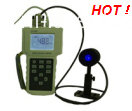
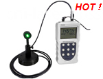
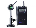
Laser Power Meter is used to measure Laser power and power stability. CNI as a world's leading designer and manufacturer of laser system, designed several laser power measurement instruments with the features of accuracy testing, easy operation, etc., which could fully meet customer's practical needs of laser power and power stability measurement. They are widely used in the research, teaching, medical science, industry and other fields.
The power can not go beyond the range of the power meter when using it.
â– Testing Instrument: Power Meter
Product
Picture
Model
Power range
Main features
Thermopile
Laser Power Meter
TS series
(Wide Range)
TS2-LP100
2mW-2W
1.
Wavelength range:
0.19-25µm
2.
Damage threshold: 40kW/cm2
3.
Power measurement range: 2mW-50W
4.
Sensitivity diameter: 22mm
5. Minimum measuring precision: 0.1mW
6.
SMA905 fiber switch connector (detachable)
TS2+TP100
TS5+LP100
2mW-5W
TS5+HP100
TS15+LP100
5mW-15W
TS15+TP100
TS35+LP100
10mW-35W
TS35+TP100
TS50+LP100
10mW-50W
TS50+TP100
HS series
(High Precision)
HS1+LP100
HS1+TP100
10mW-35W
HS5+LP100
HS5+TP100
10mW-50W
Photoelectric
Laser Power Meter
PS 100 series
(High Precision)
PS100
2mW-100mW
1. Easy operation, economic price and portable device.
2. Wavelength range: 400-1100nm
3.
Available for customizing
1-3 kinds of wavelengths
PM/PPM series
(Economical Type)
PPM Desktop
100/500/3000
mW
PM Hand-held
100/500/3000
mW


â– Examples of Testing Results

Laser Power Meter
Laser Power Meter,Handheld Laser Power Meter,Laser Energy Meter,High Power Laser powermeter
Changchun New Industries Optoelectronics Technology Co., Ltd. , http://www.lasersciences.com