Most gas-fired lime kilns at home and abroad use blast furnace gas and coke oven mixing or converter gas and coke oven gas mixing to calcine lime under normal conditions. Due to changes in the process conditions of converter, blast furnace and coke oven production, gas output will be unstable, so that the mixture ratio of mixed gas will change accordingly, and the change of mixture ratio will change the density of mixed gas. However, the commonly used gas flow detection instrument in the project is a throttling type flow meter, while the throttling type flow meter uses the gas density as a constant when measuring the gas flow, which is bound to cause a certain measurement error.
At present, both domestic and international flowmeters have a large share in the detection of lime kiln gas flow, especially in China, where the proportion of throttle flowmeters is larger. In addition, the detection of the flow rate of the mixed gas with non-fixed mixing ratio is also a technical difficulty in the measurement of industrial flow. Therefore, this paper mainly deduces the density compensation algorithm in the mixed gas flow detection in the sleeve lime kiln and briefly explains how this algorithm is applied in practice. This will help improve the accuracy of the lime gas kiln gas flow detection and stabilize the calcination temperature in the lime production process, which in turn will increase the lime quality and reduce energy consumption.
1 Analysis of Gas Flow Detection System
For ease of analysis, Meishan lime kiln is the subject of this study. Meishan lime kiln adopts a sleeve kiln structure. The fuel is mainly converter gas. In order to increase the combustion heat value of the gas, coke oven gas is added to the converter gas. The following figure shows the Meishan lime kiln gas flow detection diagram.
As can be seen from Figure 1, the kiln type of this Meishan lime kiln is a sleeve lime kiln. Gas-fired tube kiln is usually fueled by converter gas (or other gaseous fuels), so that the secondary energy of steel plants can be fully utilized. The converter gas enters the upper and lower combustion chambers together with the air and the resulting hot gas enters the sleeve kiln. In the center of the kiln, there is a vertical or hanging cylinder, which is the upper and lower inner sleeve shown in the figure, so that the calcining zone can become an annular section, which is conducive to the full calcination of lime.
The combustion chamber of the sleeve lime kiln is set up and down two layers, the upper layer is called the upper combustion chamber, and the lower layer is called the lower combustion chamber. There are 8 to 12 upper and lower combustion chambers, 12 in the figure.
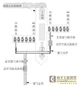
Fig.1 Schematic diagram of the sleeve lime kiln gas flow detection system
The gas supply method of the lime kiln is to supply gas to all the branch pipes from a main pipe. Each branch of the combustion chamber supplies gas to the branch pipes. In order to simplify the drawing, only the #1 upper combustion chamber and the #1 lower combustion chamber are shown in Fig.1. Branches. A flow meter measures the gas flow on the main pipe, and a flow meter checks the gas flow on each pipe. There are gas regulating valves on the main and branch pipes to regulate the gas flow.
2 throttling flow meter detection principle and analysis of the causes of error
If a restrictor with a smaller flow area than the cross-sectional area of ​​the pipe is fixedly placed in a fluid-filled pipe, the pipe-in-pipe will cause local contraction when it passes through the throttle. At the constriction, the fluid flow rate increases and the static pressure decreases, so a certain pressure difference will occur before and after the throttle. Practice has proved that for a certain shape and size, a certain pressure measurement position and straight pipe sections before and after, under certain fluid parameters, there is a certain functional relationship between differential pressure before and after the throttle and the flow of the fluid. Therefore, the flow rate can be measured by measuring the pressure difference before and after the throttle.
As already mentioned, there is a certain functional relationship between the differential pressure before and after the throttling element and the fluid flow rate. If the measured flow rate of gas is, this functional relationship can be expressed as: A0 is the opening cross-sectional area of ​​the throttling element, Ï1 - the fluid density at the inlet end of the throttling element, and (p1-p2) is the pressure difference from the actual pressure taking position. When calculating the gas flow, the throttling flow meter takes α, A0, Ï1, and ε as constants. Actually, the flow coefficient α, the coefficient of expansion ε, and the density Ï1 are not constant, and these quantities are related to changes in the temperature, pressure, and composition of the gas to be measured. The accuracy of A0 can be ensured by accurately measuring the opening diameter of the throttling element; the flow coefficient α is determined experimentally; it is difficult to measure the coefficient of expansion ε online, but when the differential pressure and the pressure of the fluid itself are small, the change can be can be ignored. Therefore, from the above analysis, we can see that in the actual measurement, even if the values ​​of α and ε change, we cannot apply the influence of the change.
It can be seen from formula (1) that the density and pressure difference are in the same position when measuring the flow rate. If the density value is inaccurate, even if the measurement of the pressure difference has a non-negligible effect on the flow measurement, the density of the gas is related to the temperature and pressure of the gas. Generally, the density can be calculated by using the ideal gas state equation to measure the temperature and pressure. . If the measured gas is a mixture of gases, compensation for temperature and pressure is not enough. Because when the mixture ratio of the mixed gas changes, even if the temperature and pressure do not change, the density also changes a lot. If the original parameter is still used to calculate, a large measurement error will inevitably occur. Therefore, density compensation is very important in the measurement of mixed gas flow. The measurement accuracy of the pressure difference is ensured by the throttling flowmeter itself, so the measurement error is mainly due to the error of the flow rate caused by the change of the density. As already mentioned, the throttling flowmeter takes the density as a constant when measuring the gas flow. This has little effect on the measurement of gas flow from a single gas source, because the gas composition of a single gas source can basically be stabilized within a certain range, so the density does not change much. If other gas sources are incorporated, the actual gas density changes greatly due to large changes in composition. If the gas density is still taken as a constant at this time, an error will occur. Therefore, the density needs to be compensated when measuring the mixed gas flow.
3 Density compensation algorithm for mixed gas flow metering
Gas measurements are more complicated than liquids because the gas is compressible. Changes in the state of the gas will cause changes in the density. From the above analysis, it can be seen that the density has a great influence on the flow meter. Through the above analysis of the throttle flowmeter error, we can see that the density and pressure difference have a greater impact on the detection accuracy of the throttle flowmeter. The measurement accuracy of pressure difference is guaranteed by the throttling flowmeter itself. The density of gas has a great relationship with the changes of temperature and pressure, so the on-line compensation of gas flow of each branch can be realized through the compensation algorithm of density, temperature, and pressure.
3.1 Density Compensation System Design
The idea of ​​using the density compensation algorithm is to add a very high-precision reference flow meter to the gas manifold to measure the gas flow of the main pipe. Since only a reference flow meter can be added to the main pipe of FIG. 1, it is not shown here any more. According to the gas flow measured by the reference flow meter on the main pipe, the gas flow measured by the throttling flow meter on the main pipe, and the gas flow measured by the throttling flow meter on the branch pipe, the real-time flow of gas flowing through each branch pipe can be derived. Thus, the precision of the measurement of the gas flow of each branch can be improved by a high-precision reference flow meter. High-precision flowmeters generally have higher market prices, so only one is added to the general manager to save conversion costs and increase the accuracy of on-site flowmeter detection.
In this design scheme, both the reference flowmeter and the throttling flowmeter output the gas flow with a 4-20mA standard signal. The computer system collects the flow signals in real time, and then uses the compensation algorithm described below for the gas of each branch. Flow compensation.
3.2 Density Compensation Algorithm
It is assumed that the flow of the mixed gas measured by the throttling flowmeter on the main pipe is Q'V, the flow measured by the reference flowmeter increased by the total pipe is Q''V, when the gas flows through the throttling flowmeter in the design state with the density Ï1 The throttling device on the main pipe will produce a differential pressure (p1-p2). Because the throttling flowmeters on the manifold and each branch are calculated at the design density Ï1, the total gas flow Q'V displayed by the throttling flowmeter on the manifold is: If the gas flows through the throttling flowmeter with the density Ï2, the differential pressure generated by the throttling device on the main pipe is still (p1 - p2). At this time, the displayed flow rate on the main pipe should be calculated using the following formula. QV.
which is Because the design density of the throttling flowmeter is Ï1, the throttling flowmeter on the main pipe still calculates the mixed gas flow according to equation (2), so the flow rate displayed by the meter is still Q′V. In fact, the flow of gas on the main pipe at this time should be calculated by formula (3), that is, the actual flow on the main pipe should be QV. (3) Formula (2) is available:
  Because our design idea is to add a very high-precision flow meter on the mains to measure the total flow of mixed gas, it can be considered that the flow measured by the reference flowmeter on the main pipe is the actual flow of mixed gas.
which is In the course of conveying gas, the main pipe has little change in the state of the gas. It can be assumed that the gas density is unchanged when the gas is sent from the main pipe to each branch, so the gas density in the remaining 12 branches can still be considered as Ï2. Set the flow of the mixed gas measured by the throttling flowmeter on the 12 branch pipes to be q'1, q'2, ...q'12, and the actual flow corresponding to each branch pipe is q1, q2, ... q12. 1 as an example to introduce the density compensation algorithm, the remaining branch pipe compensation is the same, then according to formulas (3), (4), (5) can get the following formula:
  Transform the above equation to get:
  In equation (7), q'1——the gas flow measured by the throttling flow meter on branch 1; Q''V—the total gas flow measured by the base meter, Q'V ———The total gas flow measured by the main throttle meter, q1—The gas flow of branch 1 after the density compensation. Formula (7) can be used to achieve on-line density compensation for mixed gas flow on all branches.
3.3 Implementation of Compensation Algorithm
The following figure shows the compensation result:
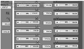
Figure 2 Compensation result In the figure, the left side is the gas main pipe and 1# to 6# gas branch pipe, the right side is the air main pipe and 1# to 6# air branch pipe, the lower combustion chamber is similar to the upper combustion chamber, and only the upper combustion chamber screen is taken for illustration in the figure. The monitoring screen can display the opening of the regulating valve and the gas flow and air flow of each branch in real time. As can be seen from the figure, the gas flow measured by the main pipe reference flowmeter is 3980m3/h, the gas flow measured by the main manifold orifice flowmeter is 4128m3/h, and the gas flow measured by the orifice flowmeter on the 1# branch pipe is 297m3. /h, then the gas flow of the compensated 1# branch pipe is 287m3/h, while the gas flow rate measured by the throttle meter on the 2# branch pipe is 285m3/h, and the corresponding compensated gas flow is 275m3/h. The measured flow of the remaining branch pipe throttling flowmeters and the compensated gas flow can be seen from Figure 2 and will not be repeated. In the field, only by associating the variables with the main flow reference flowmeter, the main flow restriction flowmeter, and the branch flow-restricting flowmeters used in the project, compensation can be realized for the flow of each branch and the compensation is displayed. Traffic.
4 Conclusion
This article does not explain what type of flowmeter is used as the reference flowmeter. Each company can select the appropriate instrument according to its actual situation. However, the selected reference flowmeter must meet two conditions: First, the flowmeter must be suitable for measuring the flow of mixed gas. The second is that the selected reference flowmeter accuracy must be very high. It can be approximated that the measured flow of the mixed gas measured by the reference flowmeter is the actual flow. If a flowmeter with the same accuracy as the original flowmeter is used to compensate it's meaningless. Based on the analysis of the causes of the measurement error of mixed gas flowmeters, this paper proposes to use a high-precision reference flowmeter to measure the main pipe gas flow to realize the density compensation program for the gas flow of each branch, and analyzes and derives the mixed gas after adding the reference flowmeter. The flow density and comprehensive compensation algorithm apply a compensation algorithm to compensate the gas flow in each combustion chamber to improve the detection accuracy of the mixed gas flow. Only adding a high-precision reference flowmeter to the mains can effectively reduce the cost of system reformation.
At present, both domestic and international flowmeters have a large share in the detection of lime kiln gas flow, especially in China, where the proportion of throttle flowmeters is larger. In addition, the detection of the flow rate of the mixed gas with non-fixed mixing ratio is also a technical difficulty in the measurement of industrial flow. Therefore, this paper mainly deduces the density compensation algorithm in the mixed gas flow detection in the sleeve lime kiln and briefly explains how this algorithm is applied in practice. This will help improve the accuracy of the lime gas kiln gas flow detection and stabilize the calcination temperature in the lime production process, which in turn will increase the lime quality and reduce energy consumption.
1 Analysis of Gas Flow Detection System
For ease of analysis, Meishan lime kiln is the subject of this study. Meishan lime kiln adopts a sleeve kiln structure. The fuel is mainly converter gas. In order to increase the combustion heat value of the gas, coke oven gas is added to the converter gas. The following figure shows the Meishan lime kiln gas flow detection diagram.
As can be seen from Figure 1, the kiln type of this Meishan lime kiln is a sleeve lime kiln. Gas-fired tube kiln is usually fueled by converter gas (or other gaseous fuels), so that the secondary energy of steel plants can be fully utilized. The converter gas enters the upper and lower combustion chambers together with the air and the resulting hot gas enters the sleeve kiln. In the center of the kiln, there is a vertical or hanging cylinder, which is the upper and lower inner sleeve shown in the figure, so that the calcining zone can become an annular section, which is conducive to the full calcination of lime.
The combustion chamber of the sleeve lime kiln is set up and down two layers, the upper layer is called the upper combustion chamber, and the lower layer is called the lower combustion chamber. There are 8 to 12 upper and lower combustion chambers, 12 in the figure.
Fig.1 Schematic diagram of the sleeve lime kiln gas flow detection system
The gas supply method of the lime kiln is to supply gas to all the branch pipes from a main pipe. Each branch of the combustion chamber supplies gas to the branch pipes. In order to simplify the drawing, only the #1 upper combustion chamber and the #1 lower combustion chamber are shown in Fig.1. Branches. A flow meter measures the gas flow on the main pipe, and a flow meter checks the gas flow on each pipe. There are gas regulating valves on the main and branch pipes to regulate the gas flow.
2 throttling flow meter detection principle and analysis of the causes of error
If a restrictor with a smaller flow area than the cross-sectional area of ​​the pipe is fixedly placed in a fluid-filled pipe, the pipe-in-pipe will cause local contraction when it passes through the throttle. At the constriction, the fluid flow rate increases and the static pressure decreases, so a certain pressure difference will occur before and after the throttle. Practice has proved that for a certain shape and size, a certain pressure measurement position and straight pipe sections before and after, under certain fluid parameters, there is a certain functional relationship between differential pressure before and after the throttle and the flow of the fluid. Therefore, the flow rate can be measured by measuring the pressure difference before and after the throttle.
As already mentioned, there is a certain functional relationship between the differential pressure before and after the throttling element and the fluid flow rate. If the measured flow rate of gas is, this functional relationship can be expressed as:
It can be seen from formula (1) that the density and pressure difference are in the same position when measuring the flow rate. If the density value is inaccurate, even if the measurement of the pressure difference has a non-negligible effect on the flow measurement, the density of the gas is related to the temperature and pressure of the gas. Generally, the density can be calculated by using the ideal gas state equation to measure the temperature and pressure. . If the measured gas is a mixture of gases, compensation for temperature and pressure is not enough. Because when the mixture ratio of the mixed gas changes, even if the temperature and pressure do not change, the density also changes a lot. If the original parameter is still used to calculate, a large measurement error will inevitably occur. Therefore, density compensation is very important in the measurement of mixed gas flow. The measurement accuracy of the pressure difference is ensured by the throttling flowmeter itself, so the measurement error is mainly due to the error of the flow rate caused by the change of the density. As already mentioned, the throttling flowmeter takes the density as a constant when measuring the gas flow. This has little effect on the measurement of gas flow from a single gas source, because the gas composition of a single gas source can basically be stabilized within a certain range, so the density does not change much. If other gas sources are incorporated, the actual gas density changes greatly due to large changes in composition. If the gas density is still taken as a constant at this time, an error will occur. Therefore, the density needs to be compensated when measuring the mixed gas flow.
3 Density compensation algorithm for mixed gas flow metering
Gas measurements are more complicated than liquids because the gas is compressible. Changes in the state of the gas will cause changes in the density. From the above analysis, it can be seen that the density has a great influence on the flow meter. Through the above analysis of the throttle flowmeter error, we can see that the density and pressure difference have a greater impact on the detection accuracy of the throttle flowmeter. The measurement accuracy of pressure difference is guaranteed by the throttling flowmeter itself. The density of gas has a great relationship with the changes of temperature and pressure, so the on-line compensation of gas flow of each branch can be realized through the compensation algorithm of density, temperature, and pressure.
3.1 Density Compensation System Design
The idea of ​​using the density compensation algorithm is to add a very high-precision reference flow meter to the gas manifold to measure the gas flow of the main pipe. Since only a reference flow meter can be added to the main pipe of FIG. 1, it is not shown here any more. According to the gas flow measured by the reference flow meter on the main pipe, the gas flow measured by the throttling flow meter on the main pipe, and the gas flow measured by the throttling flow meter on the branch pipe, the real-time flow of gas flowing through each branch pipe can be derived. Thus, the precision of the measurement of the gas flow of each branch can be improved by a high-precision reference flow meter. High-precision flowmeters generally have higher market prices, so only one is added to the general manager to save conversion costs and increase the accuracy of on-site flowmeter detection.
In this design scheme, both the reference flowmeter and the throttling flowmeter output the gas flow with a 4-20mA standard signal. The computer system collects the flow signals in real time, and then uses the compensation algorithm described below for the gas of each branch. Flow compensation.
3.2 Density Compensation Algorithm
It is assumed that the flow of the mixed gas measured by the throttling flowmeter on the main pipe is Q'V, the flow measured by the reference flowmeter increased by the total pipe is Q''V, when the gas flows through the throttling flowmeter in the design state with the density Ï1 The throttling device on the main pipe will produce a differential pressure (p1-p2). Because the throttling flowmeters on the manifold and each branch are calculated at the design density Ï1, the total gas flow Q'V displayed by the throttling flowmeter on the manifold is:
which is
which is
3.3 Implementation of Compensation Algorithm
The following figure shows the compensation result:
Figure 2 Compensation result
4 Conclusion
This article does not explain what type of flowmeter is used as the reference flowmeter. Each company can select the appropriate instrument according to its actual situation. However, the selected reference flowmeter must meet two conditions: First, the flowmeter must be suitable for measuring the flow of mixed gas. The second is that the selected reference flowmeter accuracy must be very high. It can be approximated that the measured flow of the mixed gas measured by the reference flowmeter is the actual flow. If a flowmeter with the same accuracy as the original flowmeter is used to compensate it's meaningless. Based on the analysis of the causes of the measurement error of mixed gas flowmeters, this paper proposes to use a high-precision reference flowmeter to measure the main pipe gas flow to realize the density compensation program for the gas flow of each branch, and analyzes and derives the mixed gas after adding the reference flowmeter. The flow density and comprehensive compensation algorithm apply a compensation algorithm to compensate the gas flow in each combustion chamber to improve the detection accuracy of the mixed gas flow. Only adding a high-precision reference flowmeter to the mains can effectively reduce the cost of system reformation.
Industrial Gloves Formers apply to produce industrial gloves.
Glove Mold Hand,Ceramic Industrial Gloves Former Mold,Industrial Gloves Mold,Industrial Gloves Former Mold
ZIBO HAOXIANG CERAMICS TECHNOLOGY CO.,LTD. , https://www.haoxiangceramics.com