II. Restructuring of Regulating Security System The 350 MW steam turbine of Baosteel Power Plant is provided with two high pressure main valves (TV), two reheat main valves (RSV), eight high pressure governors (GV), and two medium pressure governor doors (IV). ), Each valve is equipped with an oil motive. The oil pump is unilaterally fed into the oil. The opening of the valve's oil engine depends on the oil pressure. The closing is based on the spring force and the power oil pressure is 2.1 MPa.
The control system was modified to use DEH low-pressure turbine oil pure electro-adjustment system, which consists of electrical and EH hydraulic systems. The EH system includes the oil supply system, servo system and security system. When the hydraulic oil source is not changed during the transformation, the original oil supply system is still used, and the oil motive is not changed. The medium-pressure main valve is still controlled by the original full-open and full-close mode. Two high-pressure main valves, two medium-pressure control doors, and two high-profile doors each have an electro-hydraulic converter and a total of six electro-hydraulic converters. The security system is only partially modified.
The main points of transformation are briefly described as follows:
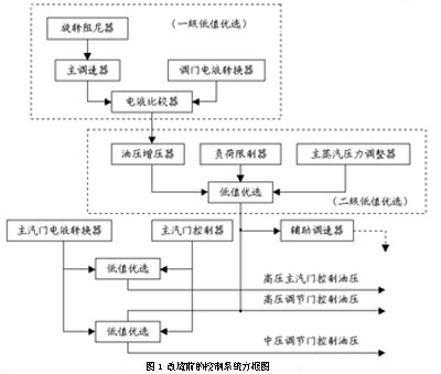
1. Adds DEH-IIIA controller (including engineer station and operator station), cancels rotary damping, main governor, auxiliary governor, load limiter, hydraulic booster, electrohydraulic comparator, electromechanical regulator , The main valve controller and other original equipment. The adjustment system was changed to computer control.
2. Adding 6 torque motor-valve-valve electro-hydraulic converters to form a one-to-two configuration with two high-pressure main-valve oil engines, eight high-pressure regulator oil engines, and two medium-pressure regulator oil engines, that is, one electro-hydraulic The converter controls 2 oil motives. One pressure transmitter is added to the control oil circuit of each electro-hydraulic converter, and a total of six are used as the hydraulic pressure feedback signal. The output signal is 4 to 20 mA.
3. One LVDT displacement sensor is installed in each throttle adjustment engine and a total of 12 valves are used as the valve opening indication.
4. The control circuit of each electro-hydraulic converter is redundantly configured with 2 OPC solenoid valves. When the turbine speeds 103% nH, it receives the signal of DEH, quickly turns off the door, inhibits the speed increase, and prevents dynamic speeding.
5. Add 2 adjustment seats, and install 3 electro-hydraulic converters, pressure gauges and globe valves on each seat.
6. Two additional AST solenoid valves have been added to provide a redundant configuration for tripping and automatically shutting down the oil pressure.
7. Six critical relays were added, and they were installed in six electro-hydraulic converters respectively. They were used to remove each of the electro-hydraulic converter control oils in case of an emergency, and to control the oil motives of each door and close the regulating valves.
8. Replace alarms for low oil pressure, low vacuum, wear of thrust bearings, and trip pressure switches.
9. Add 2 high pressure main valve active test solenoid valves.
10. Add 2 safety oil pressure switches for DEH display and interlock protection.
The block diagram of the control system before and after the transformation is shown in Figures 1 and 2.
Third, the valve servo control system works The principle of driving the steam valve servo system is the same, its working principle diagram shown in Figure 3.
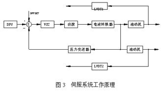
The signal output from the DEH to the VCC card is converted into a valve position command. The power amplifier performs current amplification to drive the electro-hydraulic converter and convert the electrical signal into control oil pressure. Control hydraulic pressure is converted into voltage signal by pressure transmitter. Feedback is compared with the valve position command. After the difference between the two is proportionally amplified, the current form (0-400mA) acts on the electro-hydraulic converter to form a stable The oil pressure is controlled and the oil motive is stable in the corresponding position.
Two LVDTs are fed into the amplifier terminal block and enter the DEH system to display the position of the oil motive to facilitate the inspection of the unit's operating conditions.
Transmitter setting range is 0 ~ 0.4MPa, corresponding to 4 ~ 20mA output. The oil pressure range for oil drives is 0.16 to 0.33 MPa, which corresponds to 0 to 100% of the DEH command.
When debugging, the mechanical zero of the electro-hydraulic converter is set at 0.12 MPa, that is, when the unit is reset and the DEH output command is 0, the oil pressure control of the oil machine is 0.12 MPa. When the DEH output command gradually increases to 19.05%, the power amplifier board output current is about 50mA, the corresponding valve control oil pressure is 0.16MPa, and the high pressure control valve starts to open. When the power amplifier board output current is about 250mA, adjust the door to open.
Fourth, the electro-hydraulic converter to control the hydraulic flow and response time calculation because the local transformation of our company for the first time using an electro-hydraulic converter to control the two oil motive program, for the electro-hydraulic converter flow and response time can meet the requirements, The power plant is very worried. For this, we have performed a calculation and analysis of it, and we now briefly describe the calculation results as follows:
1. Control oil flow calculation The same relay is used for all the oil motives of this machine. Calculation of leakage of oil motive relay:
When the control oil pressure is minimum, Qmin=1.25L/min
When control oil pressure is maximum, Qmax=1.484L/min
When the piston of the relay is under eccentric working conditions, the maximum leakage can reach Q'max=2.339L/min
Electro-hydraulic converter flow: throttle hole for d = 3mm, disc valve diameter D = 19.5mmQ = 16.85L/min
From the calculation results, the following conclusions are drawn: An electro-hydraulic converter can meet the requirements of two oil motive relay relays, and the leakage of two oil motives accounts for 27.7% of the electro-hydraulic converter flow. If there are more than two, it will affect the control performance of the regulating system due to the small flow margin.
2. Response time calculation oil drive piston diameter: D = 65mm
Rod diameter: d=30mm
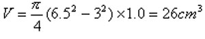
Assuming that the turbine increases the speed or load at the maximum rate, press the volume of the relay piston when it is momentarily shifted down by 10mm:
Electro-hydraulic converter dynamic flow:
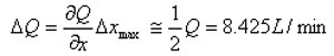
In the formula, x is the displacement of the disc valve. Because the control oil pipeline is full of oil, the response time when the relay piston is momentarily shifted down by 10mm can be estimated as follows:
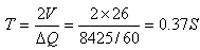
In the actual operation of the steam turbine, the increase of the speed and load is relatively slow, and it must be limited within a certain range. Even in the sudden change process, the relay piston will not have such a large stroke change of 10mm, so 0.37 The S-time response to the turbine speed and load control is sufficient to meet the requirements.
V. Reliability Design In order to ensure the safety and reliability of the unit, we not only ensure that the system strives to be advanced, efficient, and concise in meeting the requirements of the control system. At the same time, it also takes into account the crew's safety in extreme conditions. To this end, the following aspects are included in the scope of implementation during system design:
1. All electro-hydraulic converters are designed to shut down the controlled oil motor when the power is lost. In other words, once the system is de-energized, the control port of the electro-hydraulic converter is opened and the control oil pressure is rapidly reduced. The oil motive and the valve are quickly closed under the action of the spring force to ensure the safety of the unit.
2. AST jump solenoid valve redundant configuration. Keep the AST solenoid valve (S/16) on the original manual jumper oil. In addition, two AST solenoid valves (S/9) are additionally installed on the automatic oil shutoff line. Since the automatic shut-off oil circuit directly controls the operation of the critical relay, even the S/16 solenoid valve refuses to act or the relay spool valve in the mechanical shutoff device The card can still guarantee the safety of the unit.
3. OPC solenoid valve redundancy configuration. Two OPC solenoid valves are added to the control oil circuit of each adjustable gate electro-hydraulic converter to ensure the operational reliability and rapidity of the oil motive force when the unit is loaded.
4. All valves are capable of online activity testing through oil motives. After the transformation, the original high-pressure main valve manual movement test valve is changed to a remote control solenoid valve. The activity test of each door is realized by changing the control oil pressure of the electro-hydraulic converter through the valve test logic. The medium-pressure main valve activity test method is still the same before the transformation. It should be noted that the high and medium pressure valve test logics are performed in the following order: off the door → off the main valve → open the main valve → open the door. If the turbine side valve is tested for activity, all valves on the other side can be opened.
5. In the design, the integration of the equipment is fully considered. For example, all the electro-hydraulic converters, critical relays, cut-off gates, pressure gauges, etc. are uniformly arranged on the two manifold blocks to form two sets of adjustment devices. Many oil circuit connections are designed inside the manifold to reduce external takeovers, reduce leakage points, and greatly reduce installation and maintenance work.
VI. Conclusions 1. The original equipment oil motive of the local adjustment system is a sleeve feedback single-side oil inlet motive, with good quality, high control accuracy and good stability. When it is turned on, it depends on the oil pressure and closes on the strong spring. Therefore, when the oil motive is quickly shut off, it is not affected by the oil flow rate of the main oil pump. The time constant of the oil pump is small, generally about 0.3S. The load rejection test can meet the unit dynamics. Performance requirements. Therefore, it is entirely correct and appropriate for the power plant to select a retrofit scheme for low-voltage turbine oils.
2. The practice after the transformation and commissioning of the unit proved that the DEH low-pressure turbine oil pure electric adjustment of the two units has been successfully transformed. This proves once again that the use of a torque motor disc-type electro-hydraulic converter as an electro-hydraulic interface element for low-voltage turbine oils can not only meet the requirements of control performance, but also fully satisfy the safe and reliable operation of the unit.
3. Mitsubishi's 350MW steam turbine control system has been modified to greatly simplify the original electro-hydraulic co-existing complex control system, improve the adjustment accuracy of the regulation system, increase the control function of the regulation system, and further improve the unit's automation and power plant management level. For the safety and economic operation of the unit, it will play a significant role.
4. For the first time, Xinhua Company successfully used the DEH low-pressure turbine oil pure electric control for the transformation of imported large-capacity units, which has created favorable conditions for the future transformation of various other types of units.
SGI have the expertise and machining capability to manufacture standard and complex cnc turning parts to exact customer requirements. We are a key supplier for several major companies in the aerospace, metrology, semiconductor, pharmaceutical, food manufacture and defence industry sectors. We also offer finishing as required, including anodising, zinc and nickel plating, chemical blacking and painting. Our brass Cnc Turning Parts are well approved by our clients and they will believe our capability to the Brass CNC Turning services. We will give our best cost and services your Brass Cnc Turning parts.

Brass Cnc Turning
Brass Cnc Turning,Brass Cnc Machining Part,Cnc Turning Brass Parts,Precision Brass Cnc Turning Parts
SG Industry (China) Co.,Ltd , http://www.sgindustrycn.com